

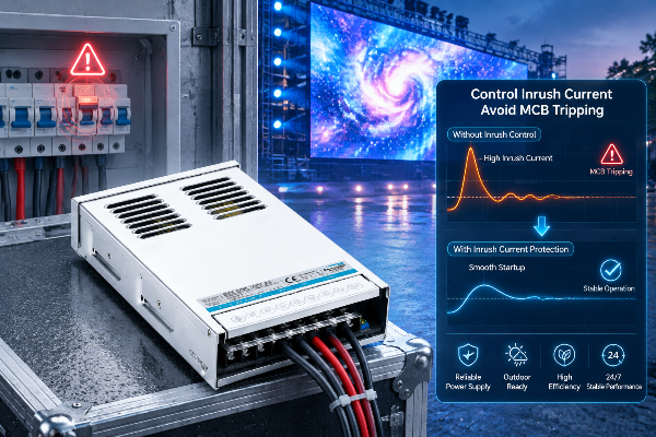
A stadium video wall in a coastal city went dark 90 seconds before kickoff. Not a controller fault, not a cable — the main distribution MCB tripped the instant the whole wall powered on. Three hundred cabinets, each carrying a dozen LED drivers, all drew their inrush surge within the same half-cycle. The combined peak current exceeded what the feeder breaker could ride through, and the entire 200 m² screen dropped. The fix was a 20-minute re-sequence of the cabinet contactors — but the broadcast window was already lost.
This is the “inrush current monster” every outdoor LED display owner eventually meets. It is invisible at design time, because the steady-state math looks comfortable: a 200 W driver pulls under 1 A, so a 20 A circuit should feed twenty of them. But at switch-on, that same driver can pull 80–130 A for a fraction of a second. Multiply by a thousand drivers firing together and you have a current spike in the tens of thousands of amps — enough to trip breakers, weld relay contacts, and reset controllers. This guide explains the physics, the sizing math, the failure modes competitors ignore, and a seven-point checklist to tame it.
Inrush current is the brief, extreme current surge an electronic device draws the moment it is powered on. In a switching power supply or LED driver, it is caused by the input capacitors — the EMC filter capacitor and the bulk capacitor on the power-factor boost stage — behaving like a near-short-circuit while they charge. The current spikes, the capacitors fill, and within a few milliseconds the draw collapses to the normal running value.
There are two flavors of inrush, and LED displays are dominated by the first:
| Type | Typical sources | Waveform | Duration |
|---|---|---|---|
| Capacitive | LED drivers, server PSUs, any switched-mode supply | Sharp needle pulse to charge input caps | Typically 0.1–2 ms (½–1 AC cycle) |
| Inductive | Transformers, motors, ballasts | Broader plateau from core saturation | Tens of ms to seconds |
For LED drivers the consensus figures are sobering: inrush runs 10–100× the steady-state current, peaks within the first half-cycle, and lasts roughly ½–1 cycle (1/100–1/50 s on 50 Hz). Real published driver data bears this out — a 150 W / 0.7 A Philips-class driver is documented at 130 A for 165 µs; a 220 W / 1.05 A unit at 80 A for 1 ms. That is the monster hiding inside every “low-power” LED.
A single downlight tripping a breaker is an annoyance. A video wall doing it is a catastrophe — and the physics stack against you:
⚠️ The “x100” rule of thumb: For a quick, conservative estimate, multiply a driver’s running input current by 100 to get its worst-case inrush. A 200 W driver at 240 V draws ~0.83 A running → ~83 A inrush. Three such drivers on one switch = ~249 A the breaker must survive. At display scale, that factor is what separates a clean power-up from a blackout.
A miniature circuit breaker does not trip the instant current exceeds its rating — it trips on the energy delivered, which depends on both peak and duration. That is why a 100 A spike lasting 1 ms may pass, while a lower but longer surge trips. Breakers are grouped by “trip curve” — the multiple of rated current (In) they tolerate before opening:
| MCB Type | Trip band | Typical use | Fit for LED inrush |
|---|---|---|---|
| Type B | 3–5 × In | Resistive loads, domestic | Poor — trips on LED surge |
| Type C | 5–10 × In | Mixed loads, commercial | Good baseline for displays |
| Type D | 10–14 × In | High-inrush (LED, transformers, motors) | Best for dense walls |
The trap: a B16 MCB is “rated” for 3,680 W, yet field data shows LED banks often trip it at just 10–20% of that load — because the breaker sees the inrush energy, not the running watts. And the failure is maddeningly random: if the contactor closes near the AC voltage zero-crossing, the driver’s capacitors charge hardest and flux builds fastest, producing the largest surge; close near the peak and it is milder. That is why the same wall “sometimes trips, sometimes doesn’t.”
Here is a realistic mid-size wall and how to size its feeder. Assumptions: 240 V supply, 200 W drivers (~0.83 A running, ~83 A inrush each at ×100), 12 drivers per cabinet, 100 cabinets, all on one distribution board through a single 100 A Type-D feeder MCB.
| Quantity | Running current | Worst-case inrush (×100) |
|---|---|---|
| 1 driver (200 W) | 0.83 A | 83 A |
| 12 drivers (1 cabinet) | ~10 A | ~996 A |
| 100 cabinets (wall) | ~1,000 A | >10,000 A (simultaneous) |
The running load (~1,000 A) already exceeds a single 100 A feeder — so in practice the wall is split across many sub-circuits. The point is that you must design the inrush budget per sub-circuit, not per wall. Using the documented rule of thumb that a 20 A Type-D MCB tolerates roughly 6–10 high-inrush drivers, a 100 A Type-D feeder safely handles ~30–50 drivers’ surge — meaning this wall needs roughly 50–80 subdivided feeds, each sequenced, not one giant contactor.
Rule of thumb: Drivers per MCB ≈ (MCB rating × trip-band low end) ÷ (running current × 100), then de-rate 30% for cabling and temperature.
Tripping is the visible symptom. The quieter damage is where outdoor displays really suffer:
Effective designs stack several measures — and crucially, never start by upsizing the breaker (a bigger MCB on undersized cable is a fire risk).
| Measure | How it works | Best for |
|---|---|---|
| Staged / sequential power-on | Time the cabinets’ contactors ms apart so surges don’t stack | Every large wall — primary fix |
| NTC inrush limiters / pre-charge | Negative-temp-coefficient resistor softens the initial cap charge, bypassed once warm | Driver-level and cabinet-level |
| Correct MCB curve (C→D) | Type-D tolerates 10–14×In; only after confirming cable is rated for the fault level | Distribution boards |
| Per-cabinet fusing | Local protection isolates one cabinet without dropping the wall | Walls >20 cabinets |
| Inrush-limited drivers | Drivers with declared low inrush (active limiters built in) | Specify at procurement — IP67 waterproof LED drivers |
The cheapest, most reliable cure is staged power-on: instead of one contactor slamming the whole wall live, the controller energizes cabinets in a rolling sequence (often with a brightness ramp so the eye never sees a hard flash). Each cabinet’s surge peaks and decays before the next begins, so the feeder never sees the stacked monster. Many display sending-cards and power sequencers support this natively — pair them with inrush-limited drivers and the MCB problem largely disappears.
| Scenario | Risk driver | Recommended approach |
|---|---|---|
| Stadium / arena video wall | Thousands of drivers, single switch-on | Per-section sequencers + Type-D feeders + per-cabinet fusing |
| Roadside billboard | Cold dawn restarts after outages | NTC-limited drivers + staged contactors; see LED street lighting solutions |
| Retail facade mesh | Mixed with building loads on shared board | Dedicated sub-feed, Type-C/D, isolate from HVAC contactors |
| Transport / station signage | 24/7, remote, hard to service | Inrush-limited drivers + surveillance-grade PSUs + monitored alarms |
With 20+ years of switching power supply manufacturing and CE / KC / 3C / UL certifications, HWELE builds the two product families an outdoor display power chain needs:
For a wall-scale build, HWELE’s OEM/ODM team can tailor driver inrush specs, IP ratings, and form factors to your cabinet design — and co-review your distribution scheme before fabrication. That upfront check is the difference between a wall that boots cleanly every morning and one that keeps the maintenance team guessing.
Inrush current is the brief, extreme current a driver draws at switch-on — typically 10–100× its running current for a fraction of a second — to charge its input and bulk capacitors. HWELE offers low-inrush IP67 drivers that keep this surge manageable.
Because every driver’s millisecond surge fires within the same half-cycle when one contactor energizes the wall. The summed peak can exceed the breaker’s trip-curve energy even though the running load is well within rating. A proper sizing and sequencing plan prevents it.
As a rule of thumb, a 20 A Type-D MCB tolerates roughly 6–10 high-inrush drivers; use the formula (rating × band) ÷ (running current × 100), then de-rate 30% for cabling and temperature. Split large walls into per-cabinet sub-circuits to stay safe.
Type-B trips on LED surge; Type-C (5–10×In) is the baseline; Type-D (10–14×In) is best for dense walls. Only upgrade the curve after confirming the cable is rated for the fault level — talk to our engineers for a design review.
Generally yes — more capacitance means a larger charge surge — but the ratio varies by design. Always read the declared peak (amps + µs/ms) on the spec sheet rather than assuming from wattage alone.
Yes, and it is the most reliable fix. Energizing cabinets a few milliseconds apart keeps each surge from stacking on the feeder. Most display controllers support this natively; combine it with inrush-limited drivers for best results.
They can. Low-inrush-rated photocells and sequencer relays may have their contacts welded shut by the LED surge, causing the circuit to stick on or fail intermittently. Always specify inrush-rated control gear alongside the drivers.
It can. Cold capacitors may present lower initial impedance, sharpening the pulse, and outdoor walls often cold-start together after a night outage. Choose temperature-rated outdoor drivers and sequence the restart.
No. Inrush is the device’s own turn-on cap-charge spike; surge is an external transient from lightning or grid switching. They need different defenses — inrush limiting and staged power-on vs. surge protection (IEC 61000-4-5).
Use an IEC 61000-4-30 Class-A power-quality analyzer with high sampling rate — a multimeter is far too slow to catch a 1 ms pulse. Capture the peak at the feeder and at a sample cabinet to size protection accurately. HWELE engineering support can help interpret the results.
Published by HWELE — Switching Power Supply & LED Driver Manufacturer. 20+ Years of Experience. CE / KC / 3C / UL Certified.


 Optimized by Seraphinite Accelerator