

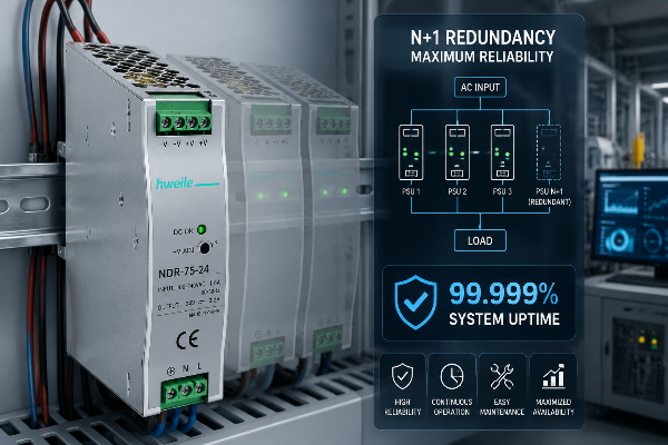
A packaging plant in Southeast Asia lost 47 minutes of production when a single 24 V DIN-rail supply feeding the line’s PLC and sensors failed during a night shift. No alarm, no warning — the bus just dropped, the line stopped, and the maintenance team spent the first 20 minutes blaming the network and the VFDs. The downtime cost was six figures. The root cause was not exotic: it was a single power supply acting as a single point of failure in a system that was never allowed to stop.
Here is the uncomfortable reality most specifiers learn late: the power supply is the one component in a control panel with no redundancy by default. Relays have spares, sensors get duplicated, networks go ring-topology — but the PSU is usually a single box. This guide fixes that. It covers what N+1 redundancy actually is, the availability math behind the famous “99.999% uptime” claim, the redundancy module that makes it work with ordinary industrial supplies, how to size and design an N+1 system, four deployment scenarios, and a 7-point verification checklist you can hand any supplier before purchase.
Redundancy vocabulary is simpler than it looks. “N” is the minimum number of power supplies needed to carry the load. The “+1” (or “+N”, or “2N”) tells you how many spares sit behind it.
| Topology | What it means | Spares | Tolerates |
|---|---|---|---|
| N (no redundancy) | Exactly the minimum PSUs; any one failing stops the load. | 0 | Nothing — single point of failure. |
| N+1 | One extra PSU beyond the minimum. If any one unit fails, the rest carry the load. | 1 | A single PSU failure (and maintenance on one unit). |
| 2N | The entire system duplicated — two independent N-capacity systems. | 100% | A whole system failure (feed, PSU bank, path). |
| 2(N+1) | Two independent N+1 systems. The gold standard for five-nines. | 2 (one per side) | A system failure and a component failure on the surviving side. |
For most industrial control panels and machine-level networks, N+1 is the sweet spot: one spare, modest cost premium, and it removes the single most common cause of power-related downtime. Data-center-grade 2N and 2(N+1) belong in tier-critical facilities — but the principle is identical, just replicated.
The famous “five nines” (99.999%) means about 5.26 minutes of downtime per year. Here is the honest progression as you add redundancy (figures consistent with published industry availability tables):
| Configuration | Typical Availability | Annual Downtime |
|---|---|---|
| Single PSU (N) | ~99.671% – 99.9% | ~9 h – 53 min |
| N+1 (one spare) | ~99.982% – 99.99% | ~1.6 h – 53 min |
| 2N (full mirror) | ~99.995% | ~26 min |
| 2(N+1) + UPS + monitoring | ~99.999% (five-nines) | ~5.26 min |
Why does adding one spare jump availability so hard? Because the failure you are now protected against — a single PSU dying — is the most likely failure in the panel. Availability is governed by MTBF (mean time between failures) and MTTR (mean time to repair):
Availability ≈ MTBF ÷ (MTBF + MTTR)
A supply with a 200,000-hour MTBF and a 24-hour MTTR (you find and swap it next shift) gives ~99.988%. But if two such supplies run in parallel through ORing modules, the chance both fail before you replace one is the product of their failure probabilities — which collapses the effective downtime. Pair that with hot-swap and a same-shift MTTR, and N+1 lands you firmly in the 99.99% band.
⚠️ Don’t be fooled by the headline: A bare N+1 stage typically delivers 99.98–99.99%, not 99.999%. Reaching five-nines requires 2(N+1) plus UPS bridging for mains loss, fast fault detection, and monitoring. If a vendor promises “99.999% from a single N+1,” ask them to show the math.
You cannot simply wire two power supplies’ outputs together. Without isolation, a failed unit back-feeds through the good one, or the two fight over load share and oscillate. The component that solves this is the redundancy module — most often built around an ORing diode (or an ideal-diode MOSFET for lower loss).
A redundancy module sits on each PSU’s output. It contains a low-forward-voltage device (Schottky diode, or an actively-controlled MOSFET “ideal diode”) that:
| Type | Forward Drop | Power Loss @ 10 A | Note |
|---|---|---|---|
| Schottky ORing diode | ~0.4–0.6 V | 4–6 W (needs heatsink) | Simple, robust, cheap. Fine for lower currents. |
| Ideal-diode (MOSFET) | ~0.02–0.05 V | <1 W | Far cooler, higher efficiency — preferred for high-current DIN-rail banks. |
This is the detail that separates a real industrial N+1 design from a marketing claim: the module must carry the full current of its PSU continuously (not just the spare’s), stay cool, and fail safe. Specify the module’s current rating with margin, and check its own MTBF — a weak module becomes the new single point of failure.
💡 HWELE design insight: Redundancy modules let you build N+1 from standard DIN-rail or enclosed supplies instead of buying expensive proprietary redundant PSUs. That is what makes control-panel-level N+1 affordable for a machine builder — not just a hyperscale data center.
| Approach | How it’s built | CAPEX premium | Best for |
|---|---|---|---|
| Parallel-redundant (ORing module) | 2+ standard PSUs paralleled through ORing modules; load shared continuously. | +15–30% | Control panels, CCTV clusters, machines — the industrial default. |
| N+1 (dedicated spare) | N units carry load, one cold/warm spare switched in on fault (often via ATS/STS). | +20–40% | Larger banks where load-share is impractical. |
| 2N / 2(N+1) | Fully duplicated independent systems, each with its own feed, PSU bank, and path. | +60–100%+ | Tier-critical medical, telecom core, financial — five-nines targets. |
For industrial networks, the parallel-redundant ORing-module approach is almost always the right answer: it uses ordinary supplies, shares load (better thermal balance and efficiency), and needs no transfer switch. Reserve 2N for loads where losing an entire feed or path is a realistic threat.
Redundancy is usually discussed for server rooms — but the failure cost is often higher on the factory floor. References cite unplanned downtime at $22,000 per minute for modern production lines (Deloitte) and average outage costs around $740,000 per incident (Ponemon). A control panel has no “retry” button; when its PSU dies, the machine stops.
Redundancy turns all of these from “one failure = stop” into “one failure = scheduled maintenance.”
Sum the continuous load (PLC + I/O + sensors + any inrush). Choose N units whose combined rated capacity at operating temperature covers the load with 20–30% headroom (derating at 50–60 °C eats capacity). Then add the spare.
Worked example: a panel needs 200 W at 40 °C. Using 100 W units derated to ~85 W at 40 °C: you need 3 units to carry 200 W (3 × 85 = 255 W ≥ 200 W with margin). That is 2+1 = N+1. Lose any one and the other two still cover the load.
In parallel-redundant (ORing) designs the healthy units share the load continuously — better efficiency per unit and cooler operation. Some architectures hold a unit in warm standby; that simplifies share control but wastes the standby unit’s thermal life unevenly. For industrial panels, continuous share is preferred.
Use hot-swappable PSUs and ORing modules so a failed unit can be pulled and replaced while the bus stays live. This is “concurrent maintainability” — you service one side without ever powering down the machine. Critical for lines that cannot stop for a PSU swap.
Redundancy handles hardware failure. Layer it with:
| Event | N (no redundancy) | N+1 with ORing modules |
|---|---|---|
| One PSU fails | Load down; line stops. | Failed unit isolated; load uninterrupted; alarm raised. |
| One input feed drops | That PSU off; load down. | If both PSUs share the feed, segment feeds; with dual feeds, unaffected. |
| Planned maintenance | Must power down the panel. | Hot-swap the unit live; concurrent maintainability. |
| Second PSU fails before swap | — | Load down (rare; this is why 2(N+1) exists for five-nines). |
The key operational win is not just survival — it is the alarm. A redundancy module (or PSU) with a dry-contact or signal output flags the fault so maintenance swaps the unit on the next shift instead of discovering it during the next failure.
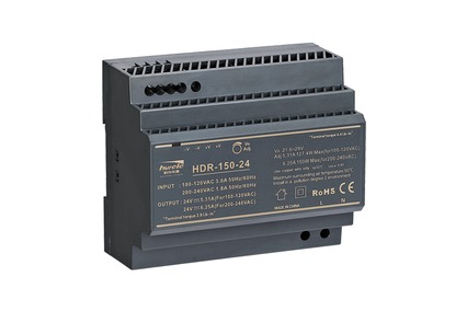
The classic case. Two NDR aluminum DIN rail power supplies on the rail, paralleled through ORing modules, feed the controller and I/O. See our industrial automation power supply solutions and our guide on DIN rail power supplies in control panels.
An NVR and camera bank fed by two paralleled supplies through ORing modules. A single PSU failure no longer creates a security blind spot. See our security surveillance power supply solutions.
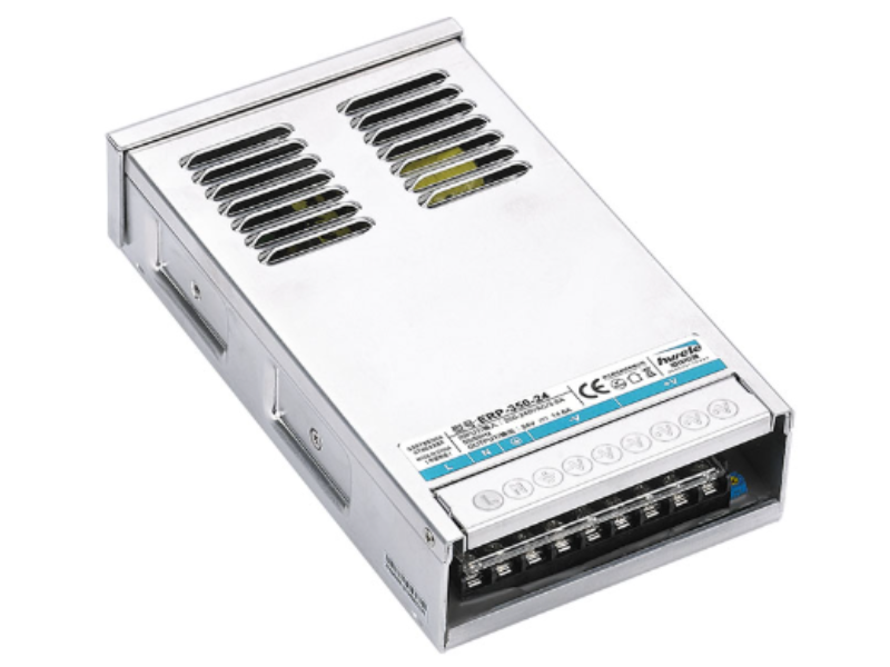
Pair enclosed switching power supplies with ORing modules inside a weatherproof enclosure, and add surge protection for the remote location. See our LED street lighting power supply solutions. A truck-roll to swap a PSU in the field is slow — redundancy buys you time.
Diagnostic and monitoring devices where interruption is unacceptable. N+1 (and for the most critical, 2(N+1)) removes the PSU as a failure mode, with the clean output and isolation such loads require.
Before signing a purchase order for any redundant industrial power system, send this to your supplier:
At HWELE, we engineer switching power supplies and LED drivers with the robustness that N+1 industrial networks demand — and our 20+ years of switching power supply manufacturing across industrial, outdoor, and surveillance applications inform every design decision. Pair any of the supplies below with a standard ORing-diode redundancy module to build a fault-tolerant N+1 bus.
| Specification | Details |
|---|---|
| Power Range | 10W – 480W |
| Redundancy Context | Rail-mount two units + ORing module for PLC / I/O N+1 |
| Recommended Rating | Hot-swap capable; size N at operating temperature + 1 spare |
| Explore | NDR aluminum DIN rail power supplies → |
| Specification | Details |
|---|---|
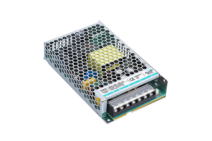
| Power Range | 10W – 600W |
| Redundancy Context | Paralleled via ORing module for CCTV clusters, machines, outdoor nodes |
| Recommended Rating | Pair with surge protection + UPS for full availability stack |
| Explore | Enclosed switching power supplies → |
HWELE provides OEM/ODM custom power supply solutions — including N+1-ready supplies, matched ORing-diode redundancy modules, hot-swap mechanicals, and fault-alarm integration — engineered to your exact control-panel, CCTV, or outdoor deployment.
20+ years of switching power supply manufacturing. CE / KC / 3C / UL certified. ISO9001 & ISO14001 quality management.
“N” is the minimum number of power supplies needed to carry the load; “+1” is one spare. If any single unit fails, the remaining units keep the load powered, eliminating the single PSU as a single point of failure. It is the standard redundancy level for industrial control panels and machine networks.
A single high-MTBF PSU gives roughly 99.9% availability. Adding a parallel spare via an ORing module and fast failure detection drives a single N+1 stage to about 99.98–99.99%. The headline five-nines (99.999%, ~5.26 minutes/year) requires 2(N+1) plus UPS bridging and monitoring for the most critical loads — a bare N+1 alone will not reach it.
A redundancy (ORing) module sits on each PSU’s output. Built around a Schottky diode or an ideal-diode MOSFET, it lets multiple supplies share the load while automatically isolating a failed or powered-down unit so it cannot back-feed or drag down the common bus. The load never sees the failure.
N+1 adds one spare and is the lowest-cost redundancy, ideal for most control panels and machine networks. 2N fully duplicates the system (two independent N-capacity paths) and tolerates a whole system or feed failure — used for tier-critical medical, telecom core, and financial loads. 2(N+1) is the five-nines gold standard.
Yes — with hot-swappable PSUs and ORing modules. You install the second unit live (the bus stays up), then you can service the first unit without powering down the machine. This “concurrent maintainability” is a key operational benefit of N+1.
Sum the continuous load, then choose N units whose combined rated capacity at operating temperature covers the load with 20–30% margin; add one spare. Example: a 200 W load using 100 W units derated to ~85 W at 40 °C needs 3 units (3 × 85 = 255 W ≥ 200 W) — that is 2+1, i.e. N+1.
In parallel-redundant (ORing) designs the healthy units share the load continuously, which improves efficiency and thermal balance. Some architectures hold a unit in warm standby; continuous load-share is generally preferred for industrial panels.
The ORing module isolates the failed unit instantly; the load is uninterrupted. A redundancy module or PSU with a dry-contact or signal output raises a fault alarm so maintenance can swap the unit on the next shift rather than discovering it at the next failure.
No. Redundancy handles PSU/hardware failure; a UPS bridges mains loss; surge protection (IEC 61000-4-5) handles transients. They are complementary layers of the same availability strategy — a redundant supply still needs UPS and surge protection to be genuinely fault-tolerant.
Yes. Pair enclosed or IP67-rated supplies with ORing modules inside a weatherproof enclosure, and add surge protection for remote telecom, LED lighting, and CCTV nodes. Redundancy is especially valuable outdoors, where a truck-roll to swap a PSU is slow and expensive.
Published by HWELE — Switching Power Supply & LED Driver Manufacturer. 20+ Years of Experience. CE / KC / 3C / UL Certified.


 Optimized by Seraphinite Accelerator