

A surveillance integrator in the Middle East spent three weeks chasing “faulty cameras.” Every few days, a different CCTV unit on a parking-garage network would freeze, show rolling horizontal bars, or reboot. They swapped cables, re-terminated connectors, and blamed the NVR. The root cause was none of those — it was the enclosed power supply feeding the camera cluster, whose output ripple rode straight on
to the 12 V bus and corrupted the video reference. A second, unrelated case: a packaging line where a PLC’s 4–20 mA analog input to a load cell drifted by 3% only when a nearby variable-frequency drive ramped up — traced to conducted EMI coupling through a shared, poorly-filtered supply rail.
Here is the uncomfortable reality most specifiers learn late: a power supply that passes safety certification is not automatically “clean.” CE, UL, and 3C confirm the unit won’t electrocute someone or catch fire. They say almost nothing about whether its switching stage emits electromagnetic interference (EMI) into your control panel, or whether its DC output carries enough ripple and noise to wreck a sensitive CCTV image or a precision analog reading.
This guide covers both threats end to end — what EMI and ripple noise actually are, how a switching power supply generates them, the international standards (CISPR 32 / EN 55032) that define “clean,” the internal filter topology that tames them, a deep-dive on ripple that no competitor article addresses, field-tested design techniques, four deployment scenarios, and a 7-point verification checklist you can hand any supplier before purchase.
Before fixing interference, you have to name it correctly — because EMI and ripple noise travel differently, fail differently, and are solved with different tools.
EMI is unwanted electromagnetic energy that disrupts the normal operation of electronic equipment. In a power supply context it shows up two ways:
And it has two modes:
Ripple is the small residual AC voltage superimposed on a power supply’s DC output. It comes from the converter’s switching action not being perfectly smoothed by the output capacitors. “Noise” is the higher-frequency spike component riding on top. Manufacturers bundle them as “ripple & noise,” measured in:
Measurement is standardized: a 20 MHz bandwidth-limited probe, tip-and-barrel grounded, across the output at rated load.
⚠️ The key distinction: EMI is about the PSU disturbing its environment (emissions — does it interfere with neighbors?). Ripple is about the PSU disturbing its own load (output purity — does it interfere with the camera or PLC it powers?). A truly “zero interference” design wins on both axes.
Not every load cares about a few dozen millivolts. A relay or a fan couldn’t tell you the difference. But CCTV and industrial-automation loads live at the microvolt edge — and that is exactly where ripple and EMI bite.
These symptoms are routinely mis-diagnosed as “bad cable” or “faulty NVR” — because the PSU looks perfectly healthy on a multimeter (which averages out ripple entirely).
💡 Design insight: A variable-frequency drive is itself a major EMI source on the plant bus. The PSU feeding your PLC must be both immune to that external noise and not add its own ripple to the load. One without the other still fails in the field.
A switching power supply chops the input at high frequency — typically 50 kHz to 500 kHz — to step voltage efficiently. That switching is the root of both problems:
Even a clean PSU sits in a noisy world: VFDs and servo drives, contactors and relays, arc welding, wireless transmitters, and even LED-lighting ballasts all pump conducted and radiated noise into shared cabling and ground. A poorly-filtered supply both emits and receives — the worst of both.
Vague “EMI compliant” claims are worthless. The benchmarks that actually matter:
| Standard | What it covers | Class / Note |
|---|---|---|
| CISPR 32 / EN 55032 | Emissions (conducted 150 kHz–30 MHz; radiated 30 MHz–1 GHz) for multimedia equipment. Replaced CISPR 22 / EN 55022. | Class A (industrial, less strict, warning required) vs Class B (residential, ~10 dB stricter). |
| FCC Part 15 (US) | Unintentional radiator emission limits — broadly aligns with Class B. | Subpart B; effectively the US Class B bar. |
| IEC / EN 61000-6 (Immunity) | Resistance to external EMI: ESD, RF fields, fast transients, surges. Connects to our surge protection guide. | A clean PSU must be immune and quiet. |
| Ripple (mVpp) | No single universal standard; stated by the manufacturer. Better units also give mVrms and a ripple spectrum. | ≤50 mVpp typical; ≤30 mVpp low-noise. |
Practical rule: Any panel installed within reach of occupied spaces — offices adjacent to a machine room, retail CCTV, medical-adjacent equipment — should target Class B with margin. Class A alone risks failing once the system is deployed near people.
A quality switching supply builds filtering into the input and output stages. The passive filter stack is what separates a quiet unit from a noisy one:
| Component | Mode Addressed | Function |
|---|---|---|
| Common-mode choke | CM | Two coils on one core oppose common-mode current, blocking noise that flows equally on both lines vs ground. |
| Differential-mode choke | DM | Inductor in series forms an LC low-pass with the X capacitor, attenuating opposite-direction noise. |
| X capacitor | DM | Across the line; safety-rated; shunts differential noise to a low-impedance path. |
| Y capacitor | CM | Line-to-ground, across the isolation barrier; shunts common-mode noise. Causes leakage current — a trade-off for medical/leakage-sensitive use. |
A filter’s performance is expressed as insertion loss in dB — how many decibels of noise it removes at a given frequency. Active EMI filters (AEF) are an emerging alternative: they inject an opposing current to cancel noise, achieving 15–30 dB of common-mode reduction in the 100 kHz–3 MHz band at a fraction of the size — useful where board space is tight.
💡 The trade-off nobody mentions: Better filtering usually means larger Y capacitors, which raise earth leakage current. In medical, intrinsically-safe, or leakage-limited installations, that matters. Ask the supplier for the leakage figure, not just the attenuation.
This is the section no reference article covers, and it is the one that most directly protects your CCTV image and your PLC readings.
The output capacitor cannot perfectly smooth the switched waveform. Its ESR (equivalent series resistance) and ESL (equivalent series inductance), plus the converter’s own switching ripple that escapes the post-filter, leave a residual AC component on the DC rail. Topology matters: crude flyback stages ripple more; LLC resonant and synchronous-rectified stages ripple less.
Ripple on the 12 V / 24 V bus is not isolated from the load. It becomes:
| Application | Recommended Ripple (mVpp) | Why |
|---|---|---|
| General digital / relay loads | ≤ 50 | Typical spec; rarely an issue for non-analog loads. |
| CCTV / IP cameras, general industrial | ≤ 30 | “Low-noise” — protects video reference and stable operation. |
| Precision analog, sensors, measurement | ≤ 20–30 | Microvolt-resolution 4–20 mA / 0–10 V inputs need a clean reference. |
A ripple number quoted at 25 °C and 100% load is not the whole story. Electrolytic capacitance drops when cold and ages when hot — so ripple often worsens at cold-start and at high operating temperature. Request the ripple specification across the minimum, rated, and maximum load, and across the full operating-temperature range. A post-regulation stage (e.g., an LDO) can clean the output further but costs efficiency — specify it only where the analog precision justifies it.
Once you have a low-EMI, low-ripple supply, the system design determines whether that cleanliness survives installation. These are the field-proven techniques:
A cluster of cameras or a PoE switch needs a clean 12 V / 24 V rail with low ripple and Class B emissions. Isolate the supply from VFD and motor runs, and ground the camera cable shields at a single point.
The panel PSU feeds analog modules, sensors, and controllers. Low ripple and conducted-emission Class B, plus a common-mode choke and clean panel ground, prevent the silent errors in Chapter 2.
Load cells, pressure transmitters, and metrology need ≤20–30 mVpp and, ideally, isolated outputs with shielded analog wiring. Treat ripple as a first-class spec, not a footnote.
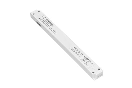
Long outdoor cable runs act as antennas for both induced EMI and conducted ripple. Pair a waterproof driver with proper grounding, surge protection, and low-ripple sourcing.
Before signing a purchase order for any CCTV or industrial-automation power supply, send this to your supplier:
At HWELE, we engineer switching power supplies and LED drivers with EMI filtering and output-purity designed into the input and output stages — not bolted on. Our 20+ years of switching power supply manufacturing across industrial, outdoor, and surveillance applications inform every filtering decision.
| Specification | Details |
|---|---|
| Power Range | 10W – 480W |
| Noise Context | PLC panels, sensors, controllers — low ripple protects analog inputs |
| Recommended Rating | Low-ripple output + internal EMI filter; CISPR 32 Class B where near occupied spaces |
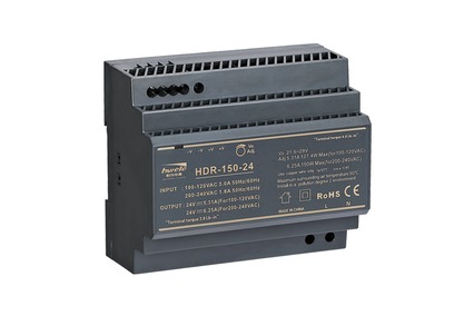
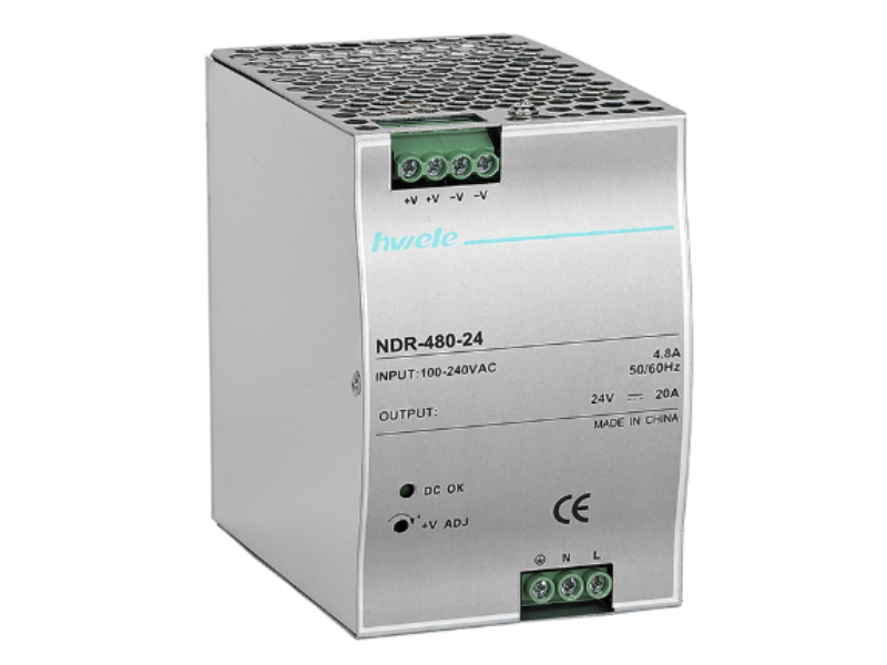
| Explore | NDR aluminum DIN rail power supplies → |
| Specification | Details |
|---|---|
| Power Range | 10W – 600W |
| Noise Context | CCTV camera clusters, PoE switches, factory automation |
| Recommended Rating | Low-ripple output + conducted/radiated emission control; verify mVpp across load & temp |
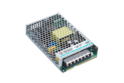
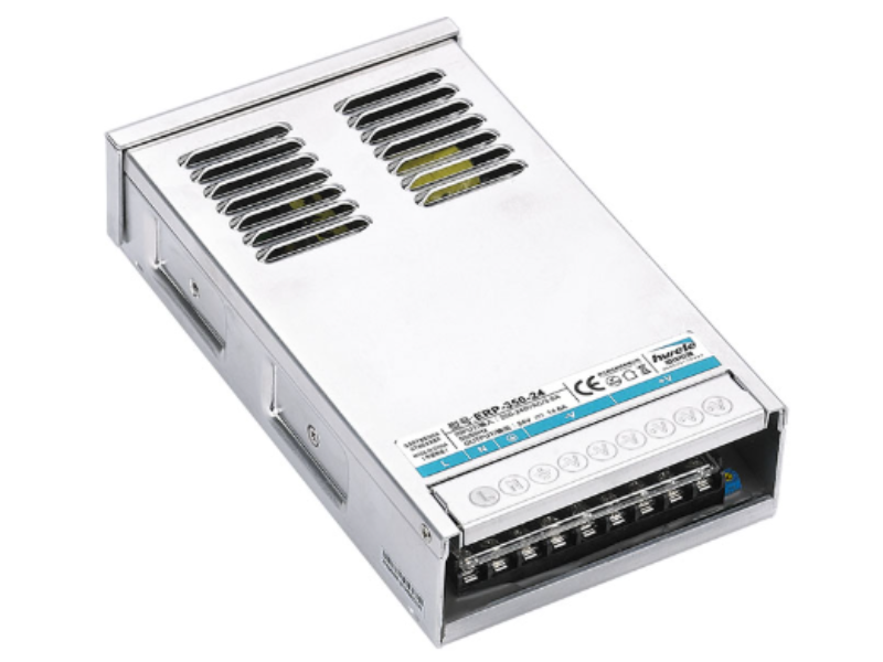
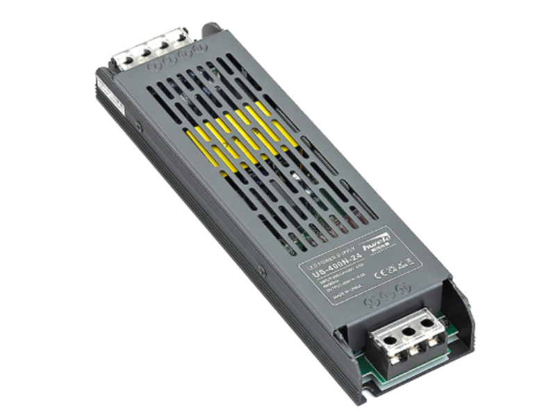
| Explore | Enclosed switching power supplies → |
HWELE provides OEM/ODM custom power supply solutions — including enhanced internal EMI filtering, low-ripple output stages, isolated rails, and ripple-verified designs — engineered to your exact CCTV or industrial-automation deployment and CISPR 32 class requirement.
20+ years of switching power supply manufacturing. CE / KC / 3C / UL certified. ISO9001 & ISO14001 quality management.
EMI is unwanted electromagnetic energy the supply emits or picks up — conducted (along wires) and radiated (through air), in common-mode or differential-mode. Ripple is residual AC voltage (measured in mVpp) riding on the DC output. EMI disturbs the environment around the PSU; ripple disturbs the load the PSU powers. A “zero interference” design must control both.
Ripple on the 12 V / 24 V bus injects noise into the camera’s video ground and reference, producing horizontal banding, rolling bars, snow, and unstable IR-cut focus. Under load, high ripple can also cause the camera’s DC-DC stage to brownout and reboot. A multimeter won’t catch it — it averages ripple away — so the fault is usually mis-blamed on cable or NVR.
For general digital loads, ≤50 mVpp is typical. For CCTV and general industrial use, target ≤30 mVpp (“low-noise”). For precision analog, sensors, and measurement, specify ≤20–30 mVpp. Always verify the number at minimum, rated, and maximum load and across the full operating-temperature range — not just at 25 °C.
CISPR 32 / EN 55032 sets emission limits (conducted 150 kHz–30 MHz, radiated 30 MHz–1 GHz) for multimedia equipment, replacing CISPR 22 / EN 55022. Class A is for dedicated industrial use (less strict, warning required); Class B is ~10 dB stricter for residential and near-occupied spaces. Panels near people should target Class B with margin.
Use a supply with an internal common-mode choke plus X/Y capacitor filter and CISPR 32 Class B compliance; house it in a metal enclosure; apply single-point grounding; separate power and signal cable runs and cross them at right angles; add ferrite beads on noisy lines; and keep cables short. Good system design is what preserves the supply’s built-in cleanliness.
Yes. Ripple on the reference rail corrupts 4–20 mA and 0–10 V analog inputs, drifts sensor readings, causes encoder false pulse counts, and disrupts RS485/CAN bus communication — especially when a nearby VFD ramps. These “silent” errors are often mis-diagnosed as bad wiring when the PSU is the true source.
Common-mode noise flows the same direction on both lines relative to ground and is the stronger radiator — usually the reason products fail radiated testing. Differential-mode noise flows oppositely on the pair and mainly distorts data and analog signals. Effective supplies address both with a common-mode choke (CM) and an LC stage with X capacitors (DM).
A common-mode choke opposes common-mode current; a differential-mode choke and X capacitor form an LC low-pass that attenuates differential noise; Y capacitors shunt common-mode noise to ground. The filter’s performance is its insertion loss in dB at each frequency. Active EMI filters cancel noise with an injected opposing current for compact, high-attenuation designs.
Grounding a shield at both ends closes a ground loop: the potential difference between the two ground points drives circulating current through the shield, injecting noise and potentially faulting the processor. A single-point ground breaks the loop while still providing the shielding benefit. The shield should also never connect to the logic common.
Yes. Long outdoor cable runs act as antennas for both induced EMI and conducted ripple, and waterproof enclosures can complicate shielding and grounding. Pair waterproof drivers with proper single-point grounding, external surge protection, and a low-ripple source — and keep the camera/signal cable shields grounded at one end only.
Published by HWELE — Switching Power Supply & LED Driver Manufacturer. 20+ Years of Experience. CE / KC / 3C / UL Certified.


 Optimized by Seraphinite Accelerator