

Paralleling two power supplies looks like the cheapest way to buy headroom, and it is — provided you are clear about which of two very different jobs you are doing. If you want more current, the outputs have to genuinely share, which means a droop characteristic or a share bus, plus a total rating you have deliberately derated. If you want redundancy so that one failure does not stop the machine, you need OR-ing decoupling so a failed unit cannot drag the bus down with it. Confusing the two is exactly how paralleled rails end up with one unit carrying the load while the other one sits there cold.
The first reason is capacity. The rail needs more current than any single convenient unit provides, or a machine grows after commissioning and the original supply is now too small. Adding a second identical unit is cheaper and faster than redesigning around a larger one.
The second reason is availability. In a control cabinet that must not stop, two supplies each capable of carrying the load — with decoupling between them — mean a single failure becomes a maintenance ticket rather than a production stoppage. This is the classic N+1 arrangement.
These two goals are frequently confused, and the confusion is expensive. A pair wired for capacity sharing but expected to provide redundancy will drop the bus when one unit fails, because nothing isolates the fault. Always state which goal you are designing for before choosing the topology.
| Goal | What the load sees | Required element | Sizing rule |
|---|---|---|---|
| More current (capacity) | Two outputs summed on one bus | Droop or active current share | Derate the sum by about 20% |
| Redundancy (N+1) | One unit carries load, other stands by | OR-ing diode or ideal diode | Each unit sized for 100% of load |
| Both | Shared normally, isolated on fault | Share bus plus OR-ing decoupling | Derate sum AND size each for load |
Notice that the “both” column is the only one that requires both circuits. It is also the arrangement most people assume they have without having built it.
Droop sharing exploits a simple property: every supply’s output voltage falls a little as its load current rises. If two units are set to the same nominal voltage and have similar droop characteristics, they naturally settle at a shared operating point — the unit that tries to deliver more current sees its output sag, and the other picks up the difference.
It is attractively simple because it needs no extra wiring, but it is approximate. Differences in setpoint, cable resistance and temperature produce imbalance, and 10–20% is normal. That is the reason for the derating rule: you cannot safely load a droop-shared pair to the arithmetic sum of its ratings.
Practically, choose identical models from the same family — for example two NDR 120 W aluminium DIN-rail units — set their outputs as close as the adjustment allows, and keep the cable runs to the common bus equal in length and gauge.
Where the datasheet offers it, active sharing connects a low-impedance share line between units. Each supply reports its current onto the bus, and the controls adjust their setpoints until the currents match. Balance within a few percent is achievable, and the pair can be loaded closer to its combined rating.
The constraints are real. The units must be the same model and explicitly rated for share operation, the share wiring must be short and kept away from noise, and the bus must not be connected while units are energised in the wrong sequence. If the datasheet does not mention parallel or share operation, assume it is not supported — no amount of careful wiring substitutes for a control loop designed to cooperate.
OR-ing is what makes redundancy work. Each supply feeds the bus through a diode (or a MOSFET-based ideal diode), so current can only flow outward. If one unit fails short or simply switches off, its diode reverse-blocks and the other unit continues to feed the load uninterrupted.
The cost is voltage drop and heat. A Schottky diode drops roughly 0.3–0.5 V, which on a 24 V rail is about 1.5–2% of the nominal output and several watts of dissipation at high current. Two options follow: either compensate by trimming the supply output up to compensate for the drop, or use an ideal-diode (MOSFET) OR-ing module, which drops only tens of millivolts. On 24 V rails feeding sensitive electronics, the ideal diode is usually worth it.
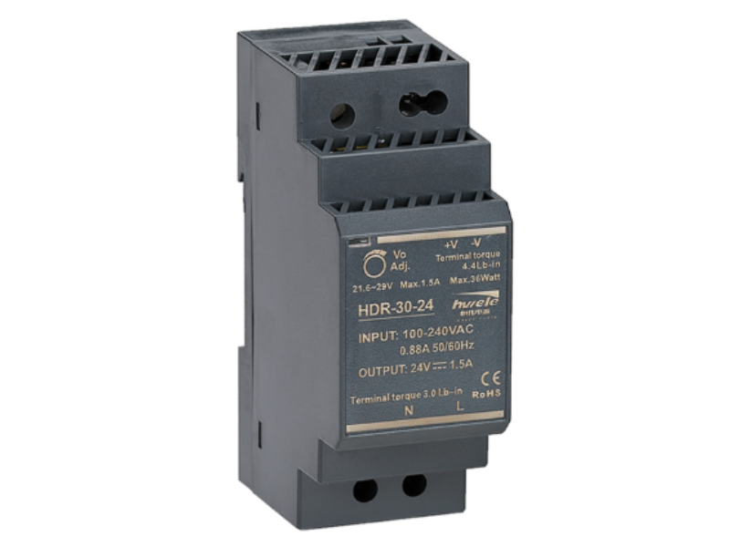
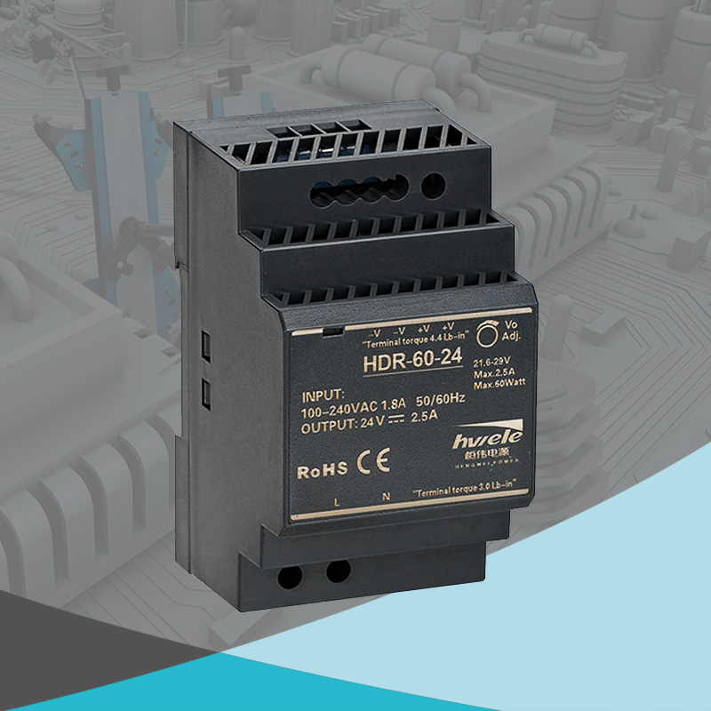
HENGWEI DIN-rail families such as the HDR 150 W and EDR 120 W are commonly deployed in paralleled and redundant cabinet rails; where redundancy is the requirement, always add OR-ing decoupling and confirm the model’s parallel statement on its datasheet.
| Scenario | Two-unit option | Combined | Usable after derating | Verdict |
|---|---|---|---|---|
| Need 24 V / 20 A (480 W) | 2 × 24 V 12 A (288 W) | 24 A | 19.2 A | Marginal — size up |
| Need 24 V / 20 A (480 W) | 2 × 24 V 15 A (360 W) | 30 A | 24 A | Comfortable |
| Need 24 V / 10 A, N+1 | 2 × 24 V 10 A | 20 A | 10 A on one unit | Correct for redundancy |
The middle row is the one people get wrong. Two 12 A units sum to 24 A on paper, but after derating for imbalance the usable figure is around 19 A — just under the 20 A requirement. The pair will run hot and eventually one unit will carry more than its share.
Q: Can I parallel any two identical supplies?
A: Only if the datasheet permits it. An identical model is necessary but not sufficient — the control loop must be designed to tolerate paralleling, whether through droop, a share bus or external OR-ing.
Q: How much should I derate a paralleled pair?
A: For load sharing, plan around 80% of the arithmetic sum. For genuine N+1 redundancy, each unit must carry the full load alone, so size each unit to 100% of the load rather than splitting it.
Q: Do I need OR-ing diodes if I only want more current?
A: Not strictly for sharing, but yes if you want any redundancy. Without decoupling, a fault on one unit takes down the entire bus — which defeats the reason most people parallel supplies in the first place.
Q: Do HENGWEI DIN-rail supplies support parallel use?
A: HENGWEI NDR, EDR, HDR and MDR DIN-rail families are used in shared and redundant cabinet rails. Confirm the parallel or current-share statement for the specific model, and add OR-ing decoupling wherever redundancy is the requirement.


 Optimized by Seraphinite Accelerator