| Model | LPV-200N-12 | LPV-200N-24 |
| Output | DC output voltage | 12V | 24V |
| Load rated output current (CC) | 16.7A | 8.4A |
| Rated output power | 200.4W | 201.6W |
| Ripple noise (Max.) | 180mVp-p | 360mVp-p |
| Voltage accuracy | ±2% | ±2% |
| Linear adjustment rate | ±0.5% | ±0.5% |
| Load adjustment rate | ±2% | ±2% |
| Start, rise, hold time 25°C | 500ms,10ms,10ms/230VAC (full load) |
| Dynamic load characteristic | Test condition: Load ≥20Hz dynamic jump. Jump range: load rated current 6%~100% |
Ripple <500mVp-p (dynamic load ripple is less than 5% of rated voltage, no obvious
audible noise, input power is stable and does not flicker) |
| Input | Operating voltage range | Optional 220VAC(200~240VAC) or 110VAC(100~120VAC)(refer to derating curve) |
| Rated operating voltage | Optional 220VAC±15%/110VAC±15% |
| Frequency range | 47~63Hz |
| Input current | <3A/110VAC;<1.7A/230VAC; |
| Power factor | PF≥0.65/110VAC, PF≥0.55/230VAC(full load) |
| Efficiency | 93.8% (full load, input 230VAC, no line damage) |
| Inrush current | Cold start current <80A/230VAC |
| Leakage current | <0.75mA/240VAC |
| Protection | Overcurrent protection | Start overcurrent protection for 105%~115% of rated output current |
Constant current limit, the current is constant, and the voltage continues to drop until it is
protected by isolation; The load can be automatically recovered after abnormal conditions
are removed |
| Overload protection | Start overload protection for 105%~115% of rated output current |
Constant power limit, the load current continues to increase or the load voltage continues
to decline, the output power is constant and the transition is to the total power decline until
the protection is isolated |
| Overtemperature protection | 110°C±10°C(Temperature sensor near switch tube) |
| Play insulation protection, can recover after temperature reduction |
| Short circuit protection | When the load impedance is 0 ohm due to an abnormal load, the system enters the
isolation protection mode, which can short-circuit for a long time |
Constant current limit, the load can be automatically restored after abnormal conditions are
removed |
| Environment | Operating temperature
and humidity | -20°C~+60°C; 20%~90%RH, no condensation |
Store temperature and
humidity | -40°C~+85°C; 10% to 95%RH, non-condensing |
Maximum enclosure
temperature | 65°C(measured at ambient temperature of 25°C) |
Shock resistance
and impact | 10Hz~500Hz, acceleration 2G 10min./1 cycle, duration 60 minutes, X, Y, Z axis for 6
sweep cycles |
| Safety | Insulation strength and
leakage current | I/P~O/P : 1.5KVAC/ < 10mA; I/P~FG : 1.5KVAC/ < 10mA;O/P~FG : 0.5KVDC/ < 10mA |
| Insulation impedance | Input and output: 10MΩ; Input and housing: 10MΩ; Output and housing: 10MΩ |
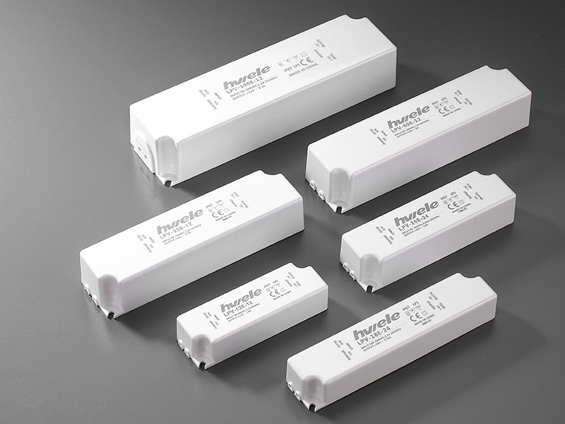
| Others | Dimension | 235*54*21mm(L*H*W) |
| Weight/packing | 0.56kg/36pcs/20.8kg/0.92CUFT/0.026cubic meters |
| Design MTBF | At 25°C, 100,000 Hrs, MIL-217 Method 2 Components Stress Method |
Design electrolytic
capacitor life | >2 years (test conditions: ambient temperature 50°C, input 230Vac, refer to derating
curve for details) |
| Note | 1. All parameters are measured at 230VAC voltage input, rated load and 25℃ when not specified.
2. Ripple and noise voltages are measured on a 20MHz bandwidth oscilloscope with a 12-inch twisted pair end and a capacitor of 0.1 μand 47 μ.
3. Voltage accuracy includes: voltage setting error, linear adjustment rate and load adjustment rate (voltage is the test value of the power port)
4. Linear adjustment rate measurement method: under rated load, from low voltage to high voltage test (voltage is the test value of the power port).
5. Load adjustment rate measurement method: from 0% to 100% rated load (voltage is the test value of the power port).
6. The power supply should be considered as part of the components in the system, and the electromagnetic compatibility should be confirmed in conjunction with the terminal equipment. |