| Model | HPV-320-12 | HPV-320-24 |
| Output | Output DC current | 12V | 24V |
Constant current range
(load CV mode) | No constant current function | 16~24V |
Constant current
(load CV mode) | No constant current function | 13.7A±0.5A |
Rated output current
(load CC mode) | 26A | 13.3A |
| Rated output power | 320W | 321.6W |
| Ripple noise (Max.) | 200mVp-p | 240mVp-p |
| Voltage accuracy | ±2% | ±2% |
| Linear adjustment rate | ±0.5% | ±0.5% |
| Load adjustment rate | ±2% | ±2% |
| Start, rise, hold time 25°C | 500ms,100ms,10ms/230VAC 1000ms,100ms,10ms/115VAC(At full load) |
| Input | Dynamic load characteristic | Test condition: Load ≥20Hz dynamic jump. Jump range: load rated current 0.07%~100% |
Ripple <1000mVP-P(dynamic load ripple is less than 5% of rated voltage,
no obvious audible noise, input power is stable and does not flicker) |
| Operating voltage range | 100~240VAC,141~339VDC(refer to derating curve); (Can withstand 300VAC surge input
for 5 seconds without damage) |
| Rated voltage range | 100VAC~240VA(refer to derating curve) |
| Frequency range | 47Hz~63Hz |
| Input current | <3A/115VAC;<1.5A/230VAC;<1.35A/270VAC |
| Power factor | PF≥0.99/115VAC,PF≥0.98/230VAC(full load) |
| Efficiency | 92.5% (full load, input 230VAC, no line loss) |
| Inrush current | Cold start current 45A/230VAC |
| Leakage current | <0.75mA/277VAC |
| Protection | Overvoltage protection | 95%~108% of the rated output current, start overcurrent protection |
Constant current limit, the load can be automatically restored after abnormal conditions are
removed |
| Overcurrent protection | Start overvoltage protection for 115%~120% of the rated output voltage |
| Turn off the output voltage and restart to restore |
| Overtemperature protection | 95°C±10°C(thermostat close to PFCA radiator) |
| Turn off the output voltage and restart to restore |
| Short circuit protection | When the load impedance is 0 due to an abnormal load, the system enters the short-circuit
protection mode and can short-circuit for a long time |
Constant current limit, the load can be automatically restored after abnormal conditions are
removed |
| Environment | Operating temperature
and humidity | -30°C~+70°C; 20%~90%RH, no condensation
(Warning: Please refer to the load derating curve for operating temperature) |
Storage temperature and
humidity | -40°C~+85°C; 10%~95%, no condensation |
Maximum enclosure
temperature | 80°C(measured at ambient temperature of 25°C) |
Shock resistance and
impact | 10Hz~500Hz, acceleration 2G 10min./1 cycle, duration 60 minutes, X, Y, Z axis for 6 sweep cycles |
| Safety | Insulation strength and
leakage current | I/P~O/P :3KVAC/10mA; I/P~FG :1.5KVAC/10mA; O/P~FG :0.5KVDC/10mA |
| Insulation impedance | Input and output: 10MΩ; Input and housing: 10MΩ; Output and housing: 10MΩ |
| Ground resistance | 32A/1 min (40A/2 min for UL certified models); Ground resistance <0.1ohms |
| Fit standard | Safety standard | Conforms to EN61347-1, GB19510 |
| EMC emission | Conforms to EN55015(CISPR22)Class B,GB/17743 Class B,GB17625.1,EN61000-3-2, -3 |
| EMC immunity | Conforms to EN61000-4-2, 3, 4, 5, 6, 8, 11 |
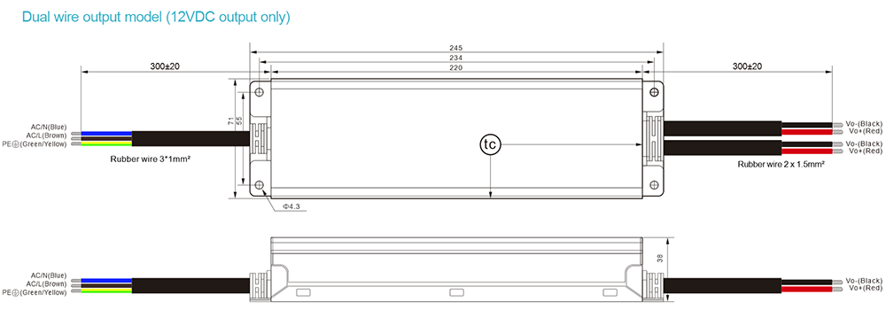
| Others | Dimension | 245*72*38mm (L*W*H) |
| Package | 1.3kg/15pcs/20.5kg/0.92CUFT/0.026m³ |
| Design MTBF | At 25°C, 100,000 Hrs, MIL-217 Method 2 Components Stress Method |
| Weight/packing | >5 years (test conditions: ambient temperature 50°C, input 230VAC, refer to derating
curve for details) |
| Note | 1. All parameters are measured at 230VAC voltage input, rated load and 25°C, unless otherwise specified.
2. Ripple and noise voltage is tested on a 20MHz bandwidth oscilloscope with a 12-inch twisted pair end and a capacitor of 0.1 μand 47 μ.
3. Voltage accuracy includes: voltage setting error, linear adjustment rate and load adjustment rate (voltage is the test value of the power port)
4. Linear adjustment rate measurement method: under rated load, from low voltage to high voltage test (voltage is the power port test value)
5. Load adjustment rate measurement method: from 0% to 100% rated load (voltage is the power port test value)
6. The power supply should be regarded as part of the components in the system, and the electromagnetic compatibility should be confirmed in combination with the terminal equipment; The specification relates to EMC standards that are only responsible for this product. |